⚡ io_decoder_eval Guide
Welcome to the io_decoder demo/eval mode guide. Follow these steps to set up your board in less than 5 minutes.
1. System Requirements
- Operating System: Linux with Real-Time kernel.
- LinuxCNC: Version 2.8 or higher.
-
Hardware: One free USB port. Arduino UNO R3.
Hardware Compatibility
The provided .hex file is specifically compiled for the ATmega328P microcontroller with a 16MHz clock.✅ **Confirmed:** Arduino Uno R3 (original and clones), Arduino Nano (5V version), and boards 100% compatible with the Uno layout. ❌ **NOT Compatible:** Arduino Mega, Leonardo, Micro, or any 32-bit board (e.g., Due, Zero, ESP32, STM32).From this point forward, this guide will refer only to the Arduino UNO.
2. Driver Installation
Download and extract io_decoder_eval-v1.zip.
Move the io_decoder.c component file and the io_decoder_eval.hex file to your preferred directory.
Move the io_decoder-keymap.cfg file into your CNC machine’s configuration folder if you wish to use the keyboard emulation functionality.
Installation Commands on Linux
- Compiling the component: Open the terminal in the folder where the component’s
.cfile is saved and type:sudo halcompile --install io_decoder.c- Define USB Port:
- Find USB Device Information Connect the device and run the command to identify its properties:
lsusbIn the command output, with the board connected, you should see a line similar to this:
Bus 001 Device 008: ID 2341:0043 Arduino SA Uno R3 (CDC ACM) - Create a udev Rule
Open a terminal and navigate to the rules directory:
cd /etc/udev/rules.d/Create a new rule for a USB serial device:
sudo nano /etc/udev/rules.d/99-io_decoder.rulesOnce executed, the terminal will open the nano text editor. The number
99tells the system to process this rule last among all existing rules. The filename99-io_decoder.rulesis a suggestion; you can choose any name as long as it ends in.rules.Paste the following rule inside the file:
SUBSYSTEM=="tty", ATTRS{idVendor}=="2341", ATTRS{idProduct}=="0043", SYMLINK+="io_decoder", MODE="0666", ENV ID_MM_DEVICE_IGNORE}="1"Press Ctrl + O to save (it will ask to confirm the filename; if it doesn’t exist, it will be created—press Enter).
Press Ctrl + X to exit the editor.Your device will now be accessible at
/dev/io_decoder, regardless of the physical port used.
If you want to change the USB symbolic link name, modify the value inSYMLINK+.WARNING > Using
MODE="0666"opens read/write permissions for the USB port to any user on the system. For higher security, you should use the terminal to create a group for USB communication with appropriate permissions and set it in the string usingGROUP="your_group_name". - Reload udev rules
sudo udevadm control --reload-rules sudo udevadm trigger - Verification
Disconnect and reconnect the device, then verify with:ls -l /dev/io_decoder
With these settings, the default value declared during the component initialization phase is satisfied.
However, everything is fully configurable.
Installation Commands for Arduino UNO R3
- How to Upload the Firmware (Flashing)
The io_decoder_eval.hex file must be transferred to the Arduino Uno’s memory. Choose the method that best suits your operating system.
Option 1: Linux (Terminal) - Recommended for LinuxCNC users
On Linux, the standard tool is avrdude. Open a terminal in the folder where you downloaded the .hex file and run:
  # Identify the port (usually /dev/ttyACM0 or /dev/ttyUSB0):
  ls /dev/tty*

  # Upload the firmware:
  avrdude -v -patmega328p -carduino -P/dev/ttyACM0 -b115200 -D -Uflash:w:io_decoder_eval.hex:i
Note: If you receive a “Permission denied” error, ensure your user is in the dialout group:
Bash
    sudo usermod -a -G dialout $USER
(Then restart your session).
- Option 2: Windows (Graphical)
If you prefer a visual interface, use XLoader (a free and lightweight tool):
1. Download and run XLoader.
2. In **Hex file**, select `io_decoder_eval.hex`.
3. In **Device**, select `Uno(ATmega328)`.
4. Select the correct **COM Port**.
5. Set **Baud rate** to `115200`.
6. Click **Upload**.
- Option 3: Arduino IDE (Advanced)
If you already have the Arduino IDE installed, you can use the included avrdude utility, although the command line remains the fastest method.
- ⚠️ Post-Loading Checks
Once the upload is complete:
- The “L” LED (connected to pin 13) on the Arduino should perform a short reset blink.
- You can now connect the Arduino to the PC running LinuxCNC and run the following command to verify it is recognized (ID 2341:0043):
- A little extra tip for you:
If you are using a cheap Arduino clone, the port on Linux might be named /dev/ttyUSB0 instead of /dev/ttyACM0. Verify this with the command:
dmesg | grep tty.
3. HAL Configuration
Add these lines to your .hal configuration file to integrate the board:
   loadrt io_decoder firmware=255
   addf io_decoder.update	servo-thread
#### Synopsis
- loadrt io_decoder [input=num] [output=num] [usb_port_name=“string”] [firmware=num] [verbose=num] [keymap_file=“string”] [uinput_chmod_cmd=“string”]
- input: In this version, the number of inputs is fixed at 4. If this parameter is provided, the value will be forced to 4.
- output: In this version, the number of outputs is fixed at 4. If this parameter is provided, the value will be forced to 4.
- usb_port_name: Allows you to name the port as desired for persistence; see the Define USB Port section. Default value:
"/dev/io_decoder". - firmware: For this version, it must be set to
firmware=255. - verbose: Enables the level of error messages displayed on the GUI. The selected number activates that message type and all lower-value levels. Default:
1.0= None.1= Component. Sends messages in case of disconnection or USB communication restart; reports keyboard functionality status.2= Minimum. Displays parsing error percentage messages.3= All.
- keymap_file: Text file to set the input => keyboard simulation mappings. Default value:
"io_decoder-keymap.cfg". - uinput_chmod_cmd: String parameter to grant write permissions on UINPUT for the simulated keyboard functionality. To ensure no permissions are granted, set the parameter to empty:
uinput_chmod_cmd="". Default value:"chmod 0666 /dev/uinput".
#### Firmware 255 (Evaluation)
- Special evaluation version for Arduino UNO R3.
- Digital Inputs: 4
- Digital Outputs: 4
- Quadrature Encoder: 1 @5Vdc
- DAC (PWM): 1 @8-bit 5Vdc
- ADC: 1 @10-bit 5Vdc
4. Testing and Diagnostics
Verify the operation by launching the LinuxCNC ‘halshow’ monitoring tool:
In the Pins section, look for:
- io_decoder.in.00 / 01 / 02 / 03: To monitor digital input signals.
- io_decoder.out.00 / 01 / 02 / 03: To toggle the state of digital outputs.
- io_decoder.enc.0: To view the encoder count.
- io_decoder.dac.0: To set the DAC value.
- io_decoder.adc.0: To read the value from the ADC.
Full list of available HAL pins.
5. Electrical Wiring for this Version
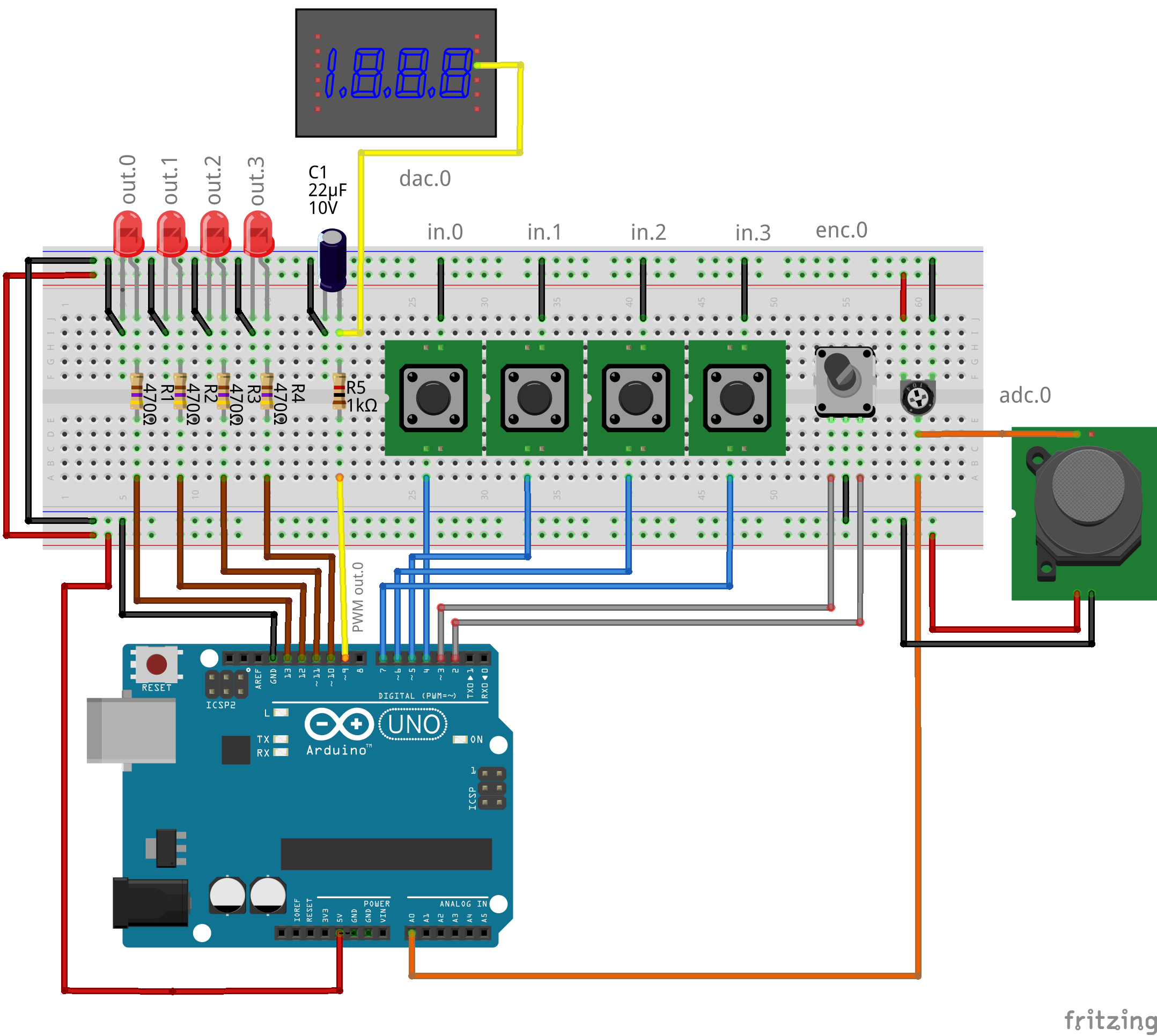
#### Arduino UNO Eval Pinout (Firmware 255)
| Pin | Function | Direction | Pull-up | Description |
|---|---|---|---|---|
| D2 | Encoder Phase A | Input | Internal | Hardware Interrupt (Phase A) |
| D3 | Encoder Phase B | Input | Internal | Digital Input (Phase B) |
| D4 | Input 0 | Input | Internal | Active Low Digital Input 0 |
| D5 | Input 1 | Input | Internal | Active Low Digital Input 1 |
| D6 | Input 2 | Input | Internal | Active Low Digital Input 2 |
| D7 | Input 3 | Input | Internal | Active Low Digital Input 3 |
| D9 | DAC (PWM) | Output | N/A | Analog Output (PWM to be filtered) |
| D10 | Output 3 | Output | N/A | Digital Output 3 (LED) max 20mA |
| D11 | Output 2 | Output | N/A | Digital Output 2 (LED) max 20mA |
| D12 | Output 1 | Output | N/A | Digital Output 1 (LED) max 20mA |
| D13 | Output 0 | Output | N/A | Digital Output 0 (Integrated “L” LED) max 20mA |
| A0 | ADC 0 | Input | No | Analog Input (0-5V) |
| 5V | VCC | Power | N/A | Sensor/Encoder Power Supply |
| GND | Ground | Power | N/A | Common Ground |
The full manual explains in depth all the configurations and possibilities of this hardware/software system for LinuxCNC.